bool task_sample_fn(Task_t * task) {
    Message_t * current_message = (Message_t *) task->state;
    current_message->u_x   = Stick::x(stick_u);
    current_message->u_y   = Stick::y(stick_u);
    current_message->m_x   = Stick::x(stick_m);
    current_message->m_y   = Stick::y(stick_m);
    current_message->flags = Stick::sw(stick_m) ? MESSAGE_LASER : 0;
    // send the message
    u8 * buffer = (u8 *) current_message;
    u16 i;
    for (i = 0; i < sizeof(Message_t); i++) {
        bluetooth->write(buffer[i]);
    }
    task->state = (void *) current_message;
    return true;
}Creating an RTOS (Pt. 3)
Using a handmade RTOS, Arduinos, and some LEDs to battle Roombas
Author's Note
This blog post is part three in a series originally put together for the University of Victoria's CSC 460 course. The original content was published April 7 2019 by Torrey Randolph and myself. As that webpage no longer exists I am now hosting the content here.
Introduction
As our final project in CSC 460 we created a semi-autonomous, remote controlled, Roomba. This project is the culmination of the lessons we learned in Project 1, where we interfaced with many of the same pieces of hardware, and Project 2, where we developed an RTOS to assist us in this project.
The Project 3 Roomba has a number of features which we needed to develop in order to compete in a final tournament between teams of similarly constructed robots. Our Roombas would attempt to defend "castle" structures whilst also doing battle with other Roombas. To achieve this goal we needed to provide the ability to:
- drive the Roomba using a joystick,
- aim and fire a laser,
- detect when we are shot by another Roomba's laser.
In addition to these features we also provide a couple of semi-autonomous features based off the project description 1, namely the ability to detect walls and infrared (IR) beams. These deliverables were split into two phases. A first phase focuses on the human-controlled features, as well as the Roomba's ability to respond to being hit with a laser. The second phase focuses on the semi-autonomous features.
To help organize, debug, and manage this project we make use of the RTOS we developed in Project 2. This RTOS is based on a Time Triggered Architecture (TTA) and, as such, our design is segmented into a series of tasks run on two Arduino boards, one attached directly to a Roomba and the second attached to a dual analog stick controller.
Software Dependencies
We took advantage of the software ecosystems provided by companies like Atmel and Arduino, as well as community created tools and libraries. Here are the major dependencies we used.
- VS Code: Visual Studio Code offered a development experience our team was familiar with as well as helpful extensions for working with Arduino hardware.
- AVR Toolchain: In order to compile code to our board outside Arduino IDE we make use of avr-gcc, a version of the GNU Compiler Collection specifically built for AVR microcontrollers. AVR Libc is the backbone of the Arduino libraries. The defacto method of uploading and downloading software to AVR boards is AVRDUDE. We use the Arduino IDE configuration file for convenience and ease of use.
- Mekpie: Our project is built using Mekpie. Mekpie is a simple C build tool written by one of our members that was updated to support building software for AVR boards.
- Saleae Logic: This is the software tool used for recording values via a Saleae USB logic analyzer. This tool is essential to collecting real-time data with little to no overhead.
In terms of code samples we also made use of Roomba code made available on Neil's Log Book 2. This code was invaluable in our interfacing with the Roomba.
Hardware
Our project made use of the following pieces of hardware. We combined this hardware using the usual suspects, breadboards, wires, and resistors.
- Create 2 Programmable Roomba: The Roomba was interfaced and controlled via one of our Arduino boards.
- 2x Arduino Mega 2560 boards: One board was used to directly interface with the Roomba, while the other was used to create a controller.
- 2x SG-90 Micro Servos in a pan and tilt module: These two servos were used to aim a mounted laser.
- 2x HC-06 Bluetooth modules: These two Bluetooth modules were used to communicate between the Roomba and the controller in phase 2.
- 2x Arduino KY-023 Joystick: One analog joystick was used to control the movement of the Roomba. The second controlled the motion of the pan and tilt module. One of the joystick buttons was also hooked up to the laser.
- Robojax Red Laser: This laser was used to shoot at other Roombas.
- Light Sensor Module: This was used to detect a laser hit.
Phase 1
In phase 1 we designed and implemented the features to control our Roomba. This mainly consisted of controlling the Roomba's movement using a joystick. Movement worked in two ways depending on the mode. In the first mode, which we called Move Mode, the Roomba can move forward, backwards, and turn on the spot, essentially free to move in whatever way the driver desires. In the second mode, which we called Still Mode, the Roomba can rotate on the spot, but cannot move forwards or backwards. The Roomba then switches between these two modes every 30 seconds as per the project specifications. This design is meant to make hitting other Roombas with a laser feasible during the tournament.
In addition to controlling the Roomba movement, a laser, mounted on a pan and tilt module, must also be controllable via a joystick. This will allow the Roomba to "attack" other Roombas by aiming its laser at their light detector. In addition, to make our Roomba "killable", we needed to provide an omnidirectional light detector that "kills" our Roomba after two continuous seconds of a laser hit. A kill results in our Roomba no longer responding to controller input and remaining still.
Design
Our design is implemented in two separate programs, one for the controller, and one for the Roomba. These two programs communicate via Bluetooth. We adapted the same messaging system as in Project 1. In this system the controller program sends the Roomba program packets containing the joystick positions and button statuses. The packet is preceded by a four byte header, which is used to synchronize the packet transmissions. New in Project 3, we introduced two-way communication by having the Roomba program send debug information back over Bluetooth. This allowed us to see debug information on a serial monitor from both programs when running. Additionally, the tracing system provided by our RTOS was usable with both programs, allowing us to easily see a trace of our tasks running, without having to plug in a logic analyzer.
Controller
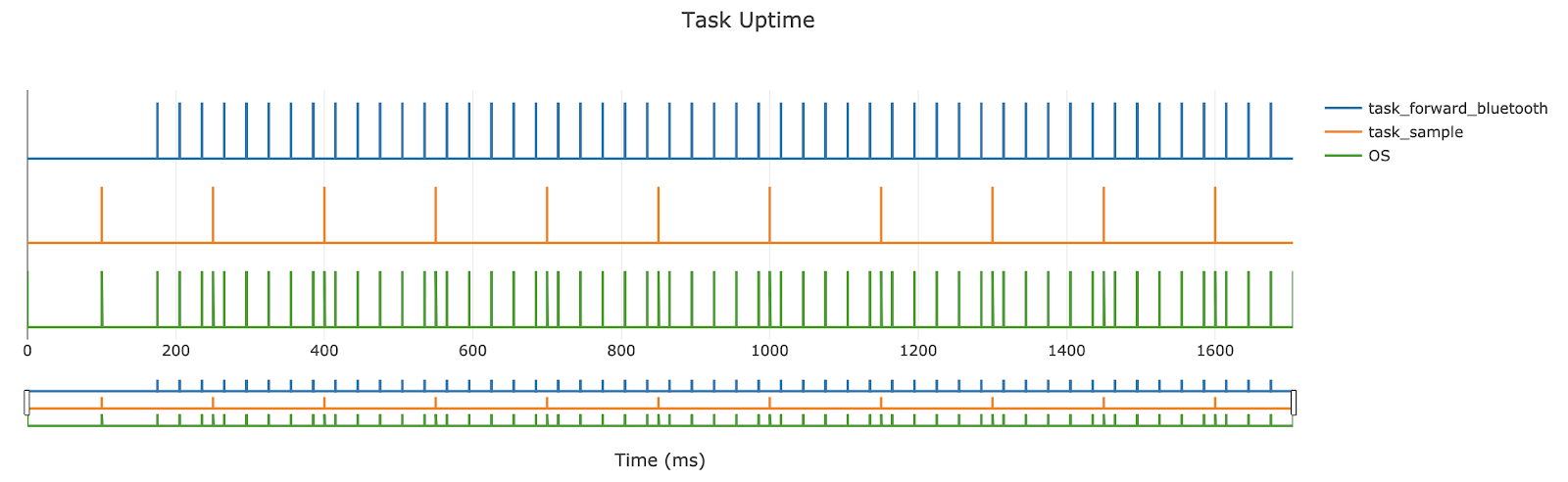
For the controller program, our design has two tasks: one for sampling inputs from the controller, and one for forwarding Bluetooth messages from the board over USB to the computer so that they could be seen on a serial monitor. Sampling input from the controller would run every 150 ms. We adjusted this value multiple times during development, but found that periods less than this did not offer much of an advantage, and produced more Bluetooth-related errors. The task that forwards Bluetooth messages had to be set to a much higher period to ensure the Bluetooth buffer did not overflow. We settled on a 30 ms period. These tasks produce the following trace:
In terms of hardware, the controller would need to connect to two analog joysticks and a Bluetooth chip. The wiring design for the controller is shown below:
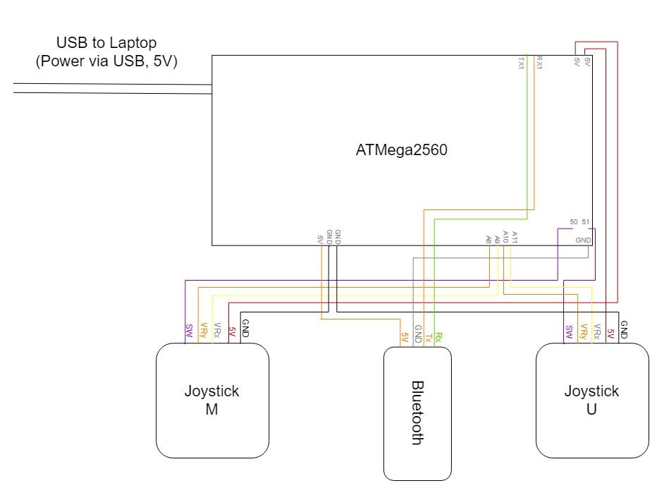
Our design is simple from a hardware perspective, and so some sampling tasks are up to software, namely we needed to provide a low pass filter for the analog sticks in order to reduce noise, and debounce the analog stick buttons. Power for our design could come straight from a laptop as the controller could remain with the user.
Roomba
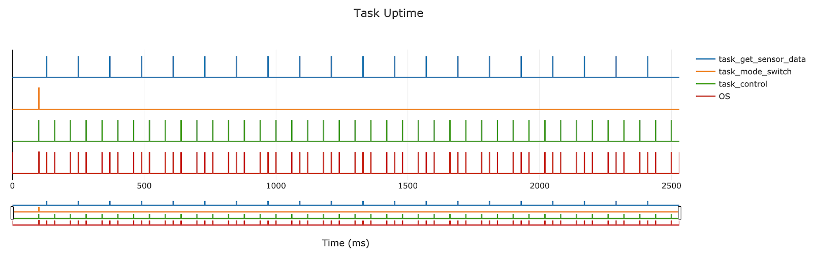
For the Roomba program, our design has three tasks: one for retrieving sensor data from the Roomba, one for switching modes, and one for controlling the Roomba, servo motors, and other peripherals. The first task, retrieving sensor data, relates to phase 2, and is discussed in more detail in that section. This task would run every 120 ms. The mode switch task would run every 30 seconds, providing an easy way to reliably switch modes without having to use an extra timer. The control task would run every 60 ms, much faster than the controller's sample task. From project 1 we learned the importance of reading Bluetooth much faster than writing to it. The control task receives messages from Bluetooth, changes the Roomba's current velocity and turning radius, adjusts the pan and tilt servos, and activates/deactivates the laser. These tasks produce the following trace:
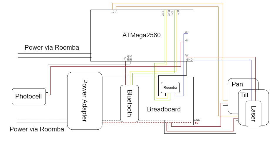
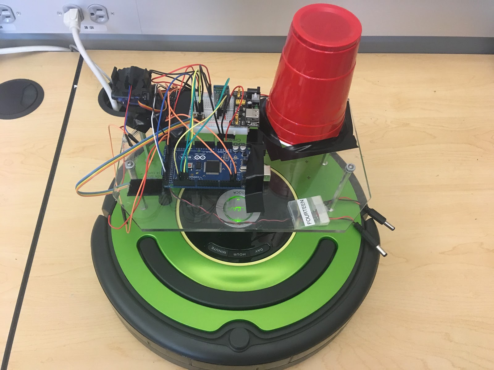
The hardware for the Roomba is somewhat more complex than for the controller. The Roomba program would run on an Arduino board powered by the Roomba's battery. The board connects to, and powers, a photoresistor, Bluetooth chip, and laser. Additionally, a pan and tilt servo module is powered separately using a power adapter and a second power connector from the Roomba. The power adapter was needed to turn the 16 V provided by the Roomba to the 5 V needed for the servo motors. Finally, in order to control the Roomba, we connected to its 7-pin port which provided us, in addition to power and ground, UART serial lines and a line used to tell the Roomba what baud rate we wanted to use. The wiring design for the Roomba is shown below:
In addition to the features already mentioned, our design would also have to detect a photocell laser hit that lasted two seconds, and prevent the laser from being fired for more than an accumulated ten seconds. We included functions for these features in the control task. More detail will be provided below.
Implementation
The controller and Roomba program implementations are largely unique programs, each having to drive unique hardware. However, they did share RTOS and messaging code. We wrote both programs concurrently, testing features one at a time. In rare cases we would create tests that relied on only one of the programs, which simplified some difficult problems.
Controller
When constructing the controller, we used a combination of a cardboard base, electrical tape, and twist ties to secure our hardware components. This resulted in a relatively comfortable to use dual analog controller, pictured below:
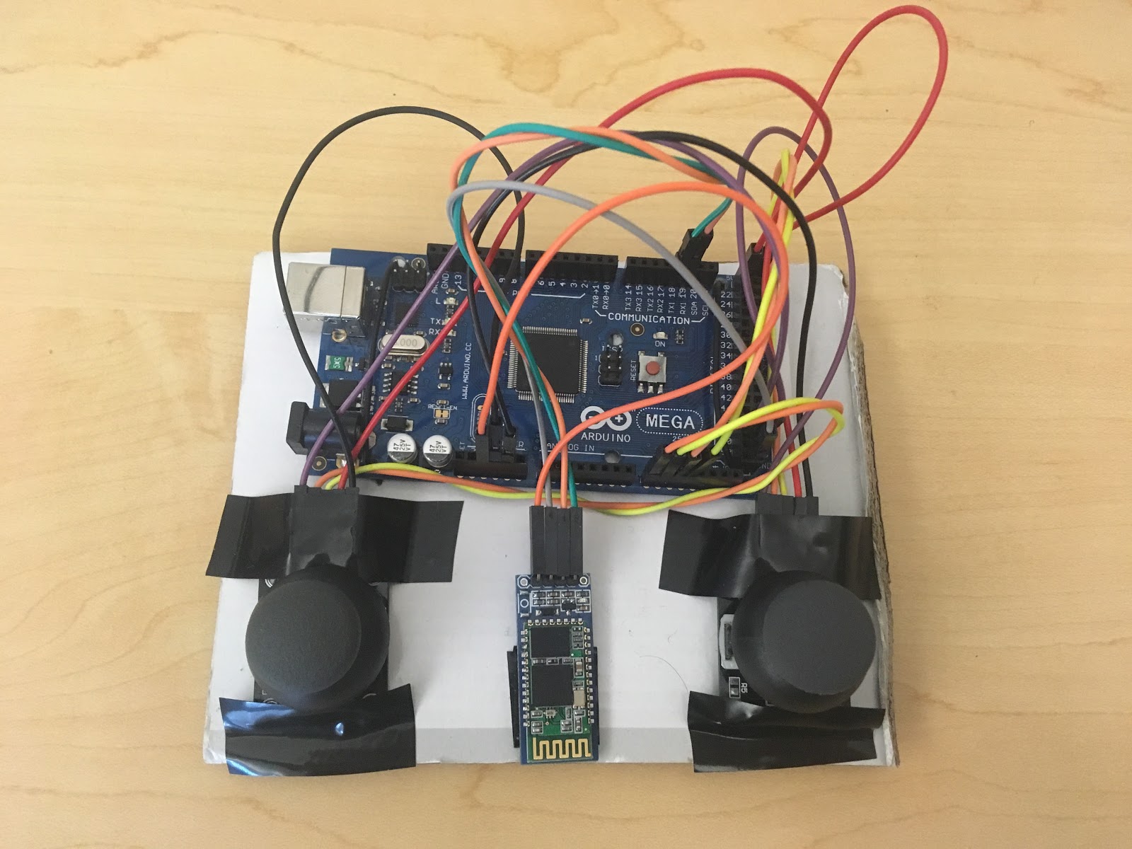
In our design, the Bluetooth forwarding task is only used for debugging. As such, our sample task can be looked at as the main loop for our controller. In it we start by sampling the x and y values from both joysticks, and then check whether one of the stick's button has been pressed. Next we write all of this data to the Bluetooth serial port. Note that this data is wrapped in a Message struct which has an unchanging 4-byte header preceding the data. In order to provide a properly initialized Message struct we took advantage of the task's state pointer to pass in an initialized Message from our main function. The code for the sample task is shown below:
12345678910111213141516
Roomba
The Roomba hardware components were attached directly to a raised platform on top of the Roomba. Most of these components were attached via electrical tape. A red cup was used to make the photocell omnidirectional. The final assembly is pictured below:
For the Roomba code, we borrowed heavily from code and advice found on Neil's Log Book 2. The code and explanations provided there made interfacing with the Roomba a relatively painless ordeal.
In terms of core functionality, we had the previously mentioned tasks for switching modes and control. For switching modes our task would toggle a boolean stored by our Roomba file as well as play a one note song to provide an audio indication to the driver that the Roomba had switched modes. Additionally, we included optional print messages for debugging over Bluetooth. The code for the mode switch task is shown below:
123456789101112131415161718
bool task_mode_switch_fn(Task_t * task) {
    if (Roomba::state == Roomba::Move_State) {
        override_control = false;
        Roomba::state = Roomba::Still_State;
        Roomba::play_song(Roomba::Still_Song);
        #ifdef PRINT_STATE
            debug_print("Roomba::state = Still_State\n");
        #endif
    } else {
        override_control = false;
        Roomba::state = Roomba::Move_State;
        Roomba::play_song(Roomba::Move_Song);
        #ifdef PRINT_STATE
            debug_print("Roomba::state = Move_State\n");
        #endif
    }
    return true;
}
For Roomba movement, we tried a number of designs. In the end we found that simpler was better. Roomba movement is governed by two parameters, radius and velocity. The Roomba can be thought of as always driving in a circle; to go straight one just needs to drive in a circle with a near infinite radius. By default we set radius to the maximum possible value. We then check if x is non-zero and if so we set the turn radius to the smallest possible value. This would effectively cause the Roomba to turn on a dime. If the Roomba is told to turn we provide it a base turn speed. In Still Mode this is the complete process. If we are in Move Mode, however, we check to see if the user has moved the stick farther in the y direction than the x direction. If so, we set the radius back to the maximum and scale the Roomba's velocity based on how far forward the stick is being held. The code for the Roomba movement is shown below:
123456789101112131415161718
i16 radius = MAX_TURN_RADIUS;
if (x > 0) {
    radius = 1;
} else if (x < 0) {
    radius = -1;
}
i16 velocity = x == 0 ? 0 : TURN_SPEED;
if (state == Move_State && abs(y) > abs(x)) {
    radius   = MAX_TURN_RADIUS;
    velocity = (((i32) y) * MAX_SPEED) / 127;
    if (x != 0) {
        if (velocity > 0) {
            velocity = clamp(velocity, TURN_SPEED, MAX_SPEED);
        } else {
            velocity = clamp(velocity, -MAX_SPEED, -TURN_SPEED);
        }
    }
}
For the photocell and laser we needed to keep track of time. This proved relatively simple as our RTOS provides a function for getting the current time in milliseconds. We simply tracked how long the photocell had been hit, and how long the laser had been on in two respective functions, and when they exceeded the maximum, took the appropriate action. For the laser that meant disabling further laser activations. For the photocell that meant stopping control and playing a short song to indicate that the Roomba had been "killed".
Drawbacks and Obstacles
We faced a number of obstacles while developing phase 1. A major problem was with our omnidirectional photocell not detecting a laser hit. We found that the light noise in the room was producing more change in our analog photocell than shining the laser on the cup was. We tried a number of fixes, including changing resistors in our voltage divider many times, trying a new photocell, and then switching to a digital photocell. The digital photocell proved much easier to work with, but suffered the same core problem that the laser simply was not producing enough light. The solution was to switch to a stronger laser. Once we realized this, detecting the laser hit became much easier.
The other core obstacle we faced during phase 1 was jerkiness and power issues with our servo motors. Our servos would twitch occasionally when powered, and we were unsure if this was a power issue or if our PWM signal was inconsistent. We looked at the signal using a logic analyzer and found that we did have some variation in the duty cycles sent to the servos, but were unconvinced that the variations were enough to cause the problems. The larger issue, however, was that, after about half a minute of the servos being on, our board would start to power cycle repeatedly, meaning we would lose Bluetooth connection and no longer be able to control our Roomba. We were unable to resolve this issue, and in the end went into the tournament without a working servo, instead relying on the Roomba movement to aim our laser.
Outside of these issues we had a couple of problems due to a bug in our RTOS regarding scheduling more than two periodic tasks. This was a test case we missed during Project 2. As soon as we determined that this was the problem, it was a relatively easy fix.
Phase 2
Phase 2 of Project 3 was to implement simple semi-autonomous behaviours for our Roomba. This included two key behaviours: backing up when hitting a wall, and backing up when hitting an IR signal, or "virtual wall". These behaviours could be achieved using sensors built-in to the Roomba, namely a front bumper and a front-mounted omnidirectional IR sensor. Overall this phase was far simpler than phase 1. However, we did have to modify our control design slightly, in that we needed to introduce a new "override state". When in this state, driver control input would be ignored, and instead the semi-autonomous behaviour, in this case driving backwards, would be performed. This state change could be managed in a similar manner to how we handled timing in phase 1 for the laser and photocell.
We also opted to have these behaviours receive a lower precedence than the Roomba's mode, ie. if the Roomba entered Still Mode and the IR sensor was activated, the Roomba would not be allowed to backup. This was achieved by having the mode switch function always exit the override state if it was enabled and ignoring sensor input during Still Mode.
Implementation
We created a new task that ran every 120 ms that polled sensor data from the Roomba. A two-state system was used; when the task was in the request state it sent four bytes over the Roomba UART connection, requesting the sensor data for the bumper and IR sensor. When the task is run again it is in the receive state, which will only read the data once two bytes have buffered in the Roomba UART connection. After this, the task switches back to the request state. The state diagram below illustrates this system.
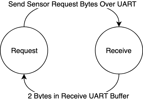
This state system is used to prevent the task from blocking, as the time it takes for the Roomba to respond to sensor data requests has some unwanted latency. Initially, this task was given a far longer period, which resulted in the sensor data we polled not picking up on short activations, such as a quick tap of the bumper. The implementation of the sensor reading is provided below.
1234567891011121314
void update() {
    static bool waiting_for_data = false;
    if (!waiting_for_data) {
        roomba_serial->write(SENSORS);
        roomba_serial->write(SENSOR_IR);
        roomba_serial->write(SENSORS);
        roomba_serial->write(SENSOR_BUMPER);
        waiting_for_data = true;
    } else if (roomba_serial->available() >= 2) {
        ir     = roomba_serial->read() ? true : false;
        bumper = roomba_serial->read() & 0b11 ? true : false;
        waiting_for_data = false;
    }
}
Drawbacks and Obstacles
The sensor system worked largely without problems. One issue with the state system, however, was that if Bluetooth cut out during a semi-autonomous behaviour the Roomba would continue to move backwards even after the override state had ended. A timeout on controller packets could have been used to resolve this issue, setting the Roomba speed to a reasonable default, like zero. However, we figured that if our Bluetooth cut out, we would have bigger problems than just the override state.
A design drawback of our solution is that if our Roomba were to back into an IR beam, it would backup through it, effectively crossing any existing IR barrier. We decided this was an acceptable limitation, however there were a number of solutions we considered developing:
- Consider the Roomba's current direction and attempt to go in the opposite direction.
- Rather than having the Roomba back up, simply have it turn 180 degrees to face the opposite direction.
- Prevent the Roomba from moving backwards at any time.
All of these solutions had problems, however, such as the 180 degree turn solution resulting in the Roomba getting itself trapped in a cycle of constantly rotating. This occurred during the final tournament to a couple other Roombas that implemented this solution. In the end we believe our simple solution was effective.
Testing and the Tournament
Our Roomba competed in a tournament that pitted it against Roombas with similar features. During the tournament, teams of two Roombas competed in a game of attack and defense. An arena was set up with two lanes, divided by an IR river, as well as two "castles" at one end. If shot by a laser these castles would be destroyed, resulting in a win for the attackers. One attacking Roomba and one defending Roomba was placed on each side of the river creating a 1v1 environment. Additionally, Roombas were outfitted with a "shield" which could be used to protect themselves and their castle, as well as using it to deflect attacks back at the enemy.
Before competing in the tournament we spent much of our time testing our Roomba features and gathering some metrics on its memory and CPU utilization.
Testing Process
During development we tested features one at a time. An essential part of the process was our use of debug messages. By forwarding messages over Bluetooth we could use the serial monitor to view information from either program while testing. For example. we could easily see what our sensor values were during phase 2, or what we thought we were setting our Roomba velocity and radius to during phase 1.
The RTOS traces were also useful for ensuring our tasks were running at the correct times and that no task was running over time. For hardware problems however, the logic analyzer still proved to be an invaluable tool.
Tournament Performance
During the tournament we placed second. Being unable to use the servo to aim our laser was not a major disadvantage. The chaos of the tournament meant that only having to worry about aiming using our Roomba made the task of control simpler, and, focusing only on killing other Roombas, we did not have to worry about the angle of our laser. Using this technique we were able to score a kill in the first game.
During the tournament we did experience some Bluetooth buffering problems. This caused our Roomba to begin to twitch after a minute or so. Thankfully, this problem could be fixed by resetting the controller, resulting in only a few moments without direct control.
The tournament itself was generally chaotic, and once Roombas were out of lasers to fire the best strategy seemed to be to try and ram the enemy Roomba into the IR river.
Other Metrics
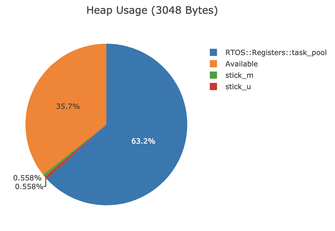
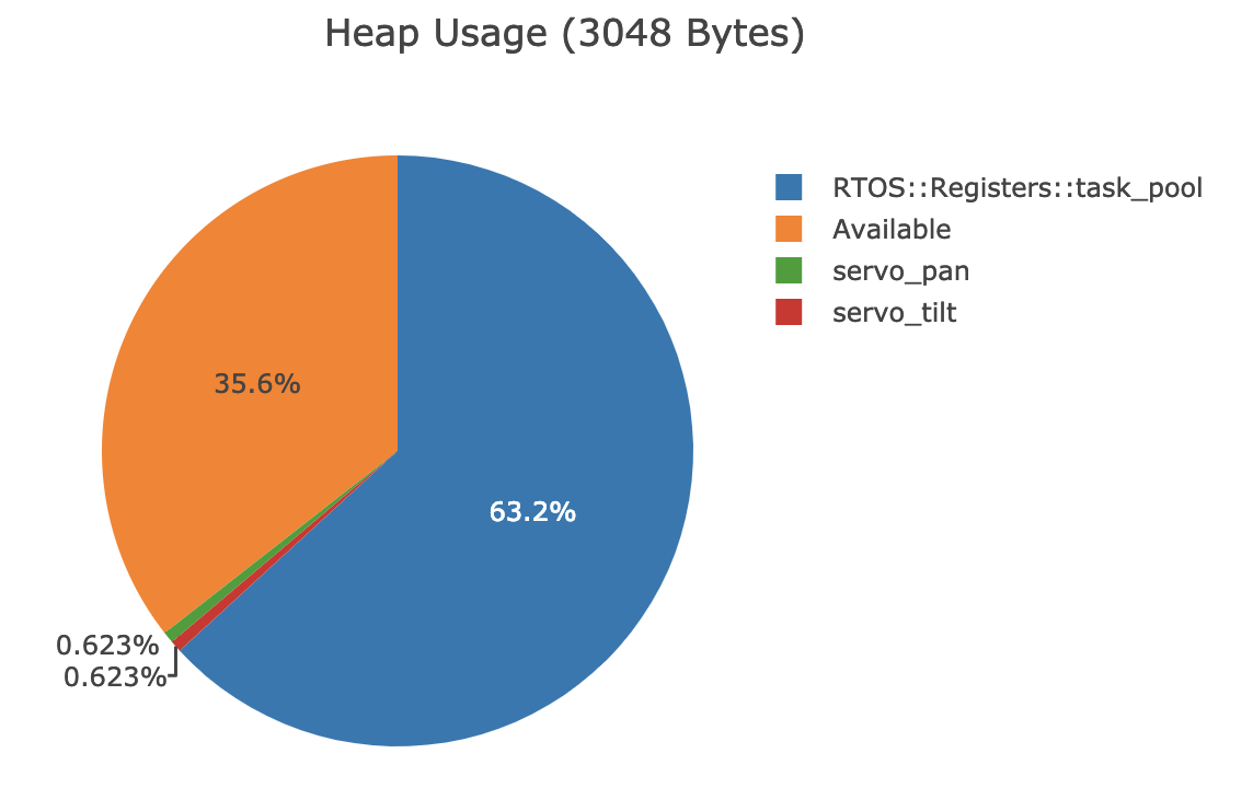
We were also able to collect data on our memory usage and CPU utilization using our RTOS. The pie charts presented here relate to our RTOS heap, not the C heap. This heap is used by our RTOS's custom allocator. Overall, memory was not much of an issue, and the main consumer of memory was our task pool, which could easily have been smaller as we only needed two tasks for the controller and three tasks for the Roomba, but had enough memory for up to sixty-four tasks. Otherwise, only a small amount of memory was used for structs that kept track of tuning parameters and state for hardware. The graphs below show the memory breakdown.
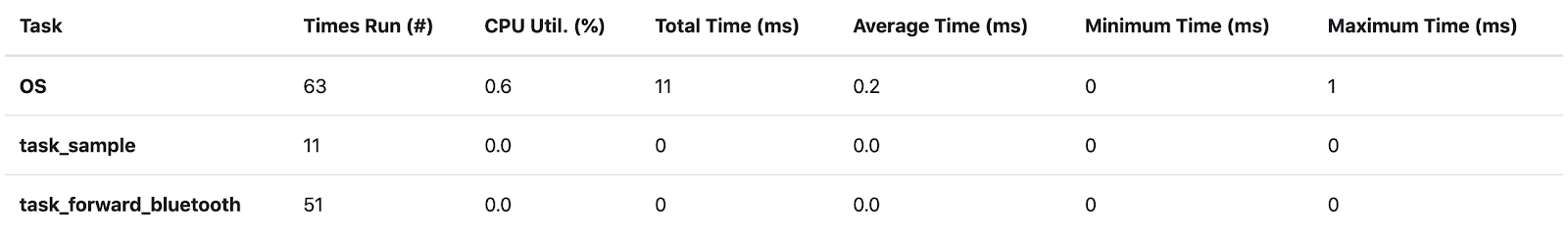
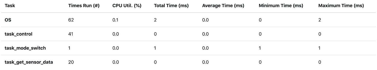
According to our RTOS tracer our CPU utilization was extremely low, 0.6% for the controller, and 0.1% for the Roomba. These measurements are likely inaccurate due to the lack of resolution less than 1 ms. Our CPU utilization is still likely very efficient, however, as no task took more than 1 ms to run, meaning that most of our time was spent with the CPU in idle mode. These CPU metrics for both programs are shown below:
Conclusion
Project 3 was an overall success despite our issues with the servos. All of our other features worked effectively. Our Roomba managed to perform well during the tournament and did not go overboard on CPU utilization. We learned a lot during this process and faced many setbacks during the development process. At least for us, the hardware generally proved more difficult than the software, though both had their fair share of challenges. This is likely just a matter of experience as neither of our team members have extensive experience with hardware.
Our RTOS from Project 2 proved extremely useful in implementing and debugging our design, however many of its more advanced features, such as event-driven tasks, and dynamic task creation, were left unused. This is because of a lesson learned many times over the course of these three projects, that simpler is almost always better when it comes to low level programming.
References
[1] M. Cheng, "Project 3", Webhome.csc.uvic.ca, 2019. [Online]. Available: https://webhome.csc.uvic.ca/~mcheng/460/spring.2019/p3.html. [Accessed: Apr-2019].
[2] "Roomba Report | Neil's Log Book", Nrqm.ca, 2019. [Online]. Available: https://nrqm.ca/roomba-report/. [Accessed: Apr-2019].